Crouds features
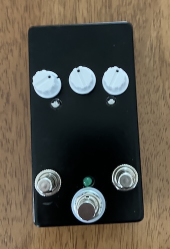
Same controls as the Electrosmith pod.
Versions
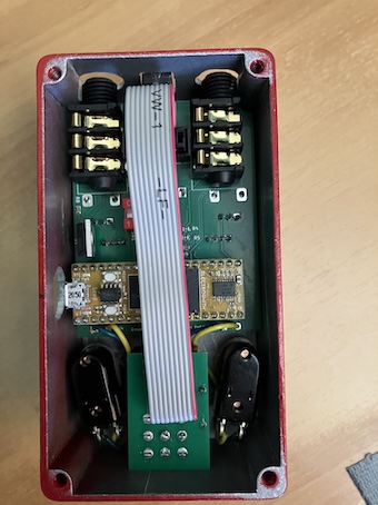
0.5
First design with surface mount resistors, capacitors and TL074. IDC ribbon connector to connect to the footswitch.
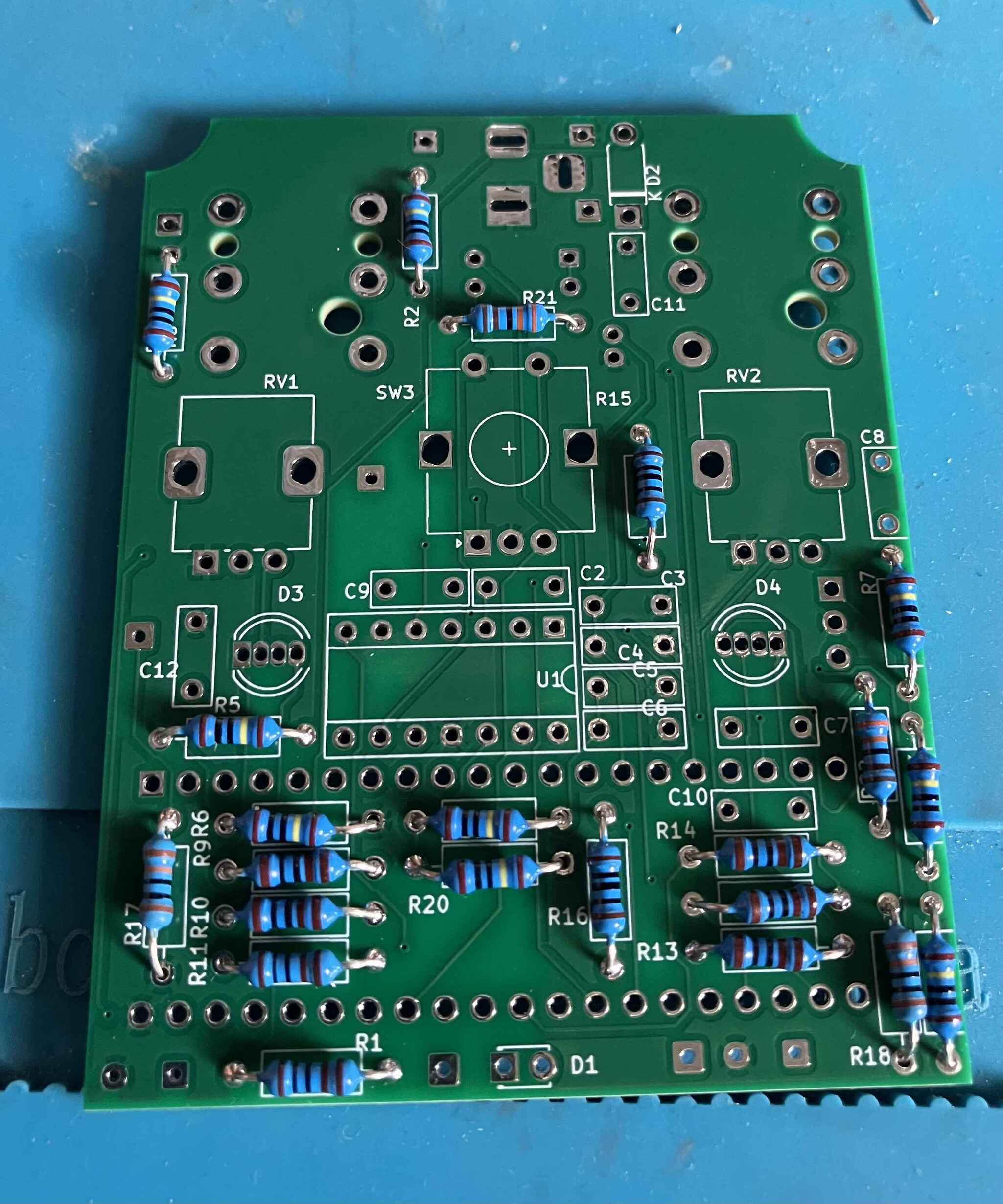
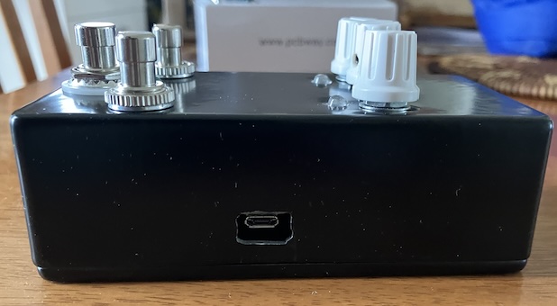
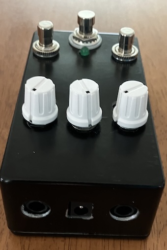
0.4
In a 125b enclosure, with a through hole design. Stereo output, mono input, with a switch to toggle between line input and guitar input.