How to build and program Crouds, the programmable pedal.
This is the multi-page printable view of this section. Click here to print.
Documentation
- 1: Getting Started
- 2: Hardware
- 2.1: Crouds 0.4
- 2.2: Crouds 0.5
- 3: Software
- 3.1: Flashing patch binaries using the web
- 3.2: Flashing Puredata patches with PlugData
- 3.3: Patch information
- 3.3.1: Blooming Sparkles
- 3.3.2: Chorus
- 3.3.3: Compressor
- 3.3.4: Overdrive
- 3.3.5: Reverb
- 3.3.6: Tap tempo delay
- 3.3.7: Tremolo
- 4: FAQs
- 5: Contribution Guidelines
2 - Hardware
Information about the pedal hardware
Crouds features
Same controls as the Electrosmith pod.
Versions
0.5
First design with surface mount resistors, capacitors and TL074. IDC ribbon connector to connect to the footswitch.
0.4
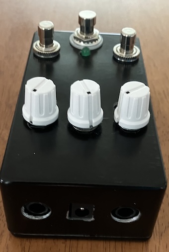
In a 125b enclosure, with a through hole design. Stereo output, mono input, with a switch to toggle between line input and guitar input.
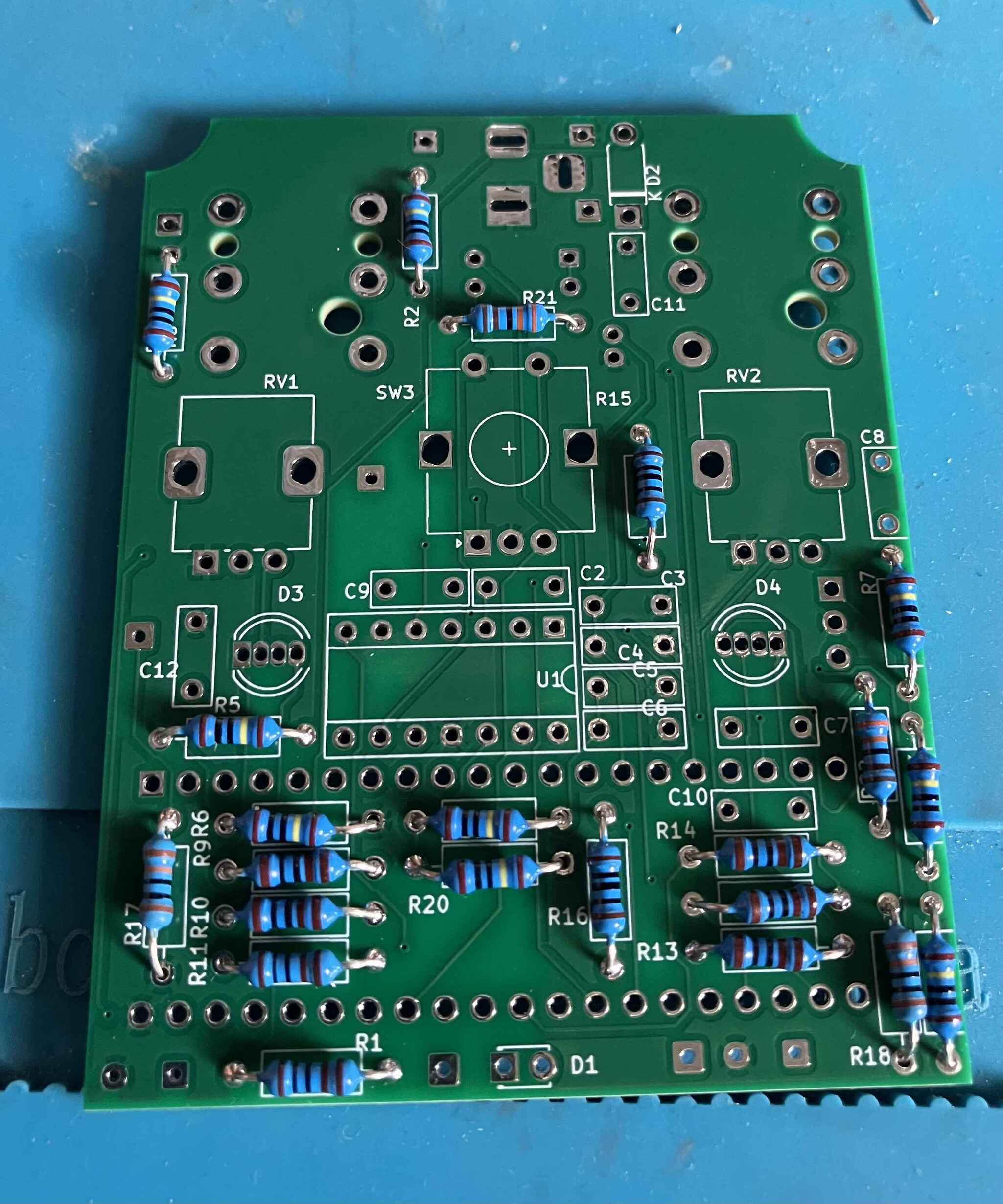
2.1 - Crouds 0.4
v0.5 of Crouds; build guide
Build guide
Through hole design. Audio and power sockets are on the PCB. Requires wiring to the footswitch.
Build order:
Resistors
Build order
- Resistors
- Diode
- Seed socket
- IC socket
- Small caps
- Large caps
- Pots and encoder
- DIP switch
- power socket
- audio input and output sockets
- Electrolytic cap
- Lm7805
- visual check (use magnifier) of all joints; use stick to check * mechanical
- power up and check 5v and VCC to Seed correct
- bypass LED
- RGB LEDs
- footswitch
- momentary footswitches
- fit TL074 and Seed
- Power up and test
- Drill enclosure
- box it up
- test
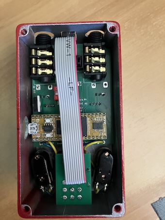
2.2 - Crouds 0.5
v0.5 of Crouds
This is the first version of the pedal with SMD resistors, caps and TL074. Speeds up the build process considerably. It also uses a footswitch PCB with IDC connector to reduce the number of separate wires connecting the footswitch to the main PCB.
Changes for 0.6
A new audio socket will be used - one with the screw on the outside that connects to the socket. A more sensible SPDT switch to toggle between guitar and line input will also be added.
3 - Software
Information about the software that runs on the Daisy
3.1 - Flashing patch binaries using the web
How to patch using Electrosmith’s web tool
You can download existing patch binary file (.bin) from https://github.com/motekulo/prog1/tree/main/patches/pd then flash them to your pedal using the web interface at https://flash.daisy.audio/.
If the Daisy Seed in your pedal has not yet been flashed with an effect, then you need to load a bootloader first.
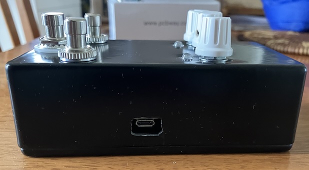
Important - when flashing, power your pedal from just the USB port - not the main 9v power as well.
- Plug the pedal into the computer using a micro usb cable. You don’t need any other power source to the pedal for this part of the process.
- Prepare the Daisy for flashing by holding the boot button, then pressing and releasing the reset button (while still holding the boot button). Release the boot button and the Daisy will be ready.
- Go the bootloader tab at https://flash.daisy.audio/ and select v6.3.
- Press the flash button on the web interface
Once you have a bootloader, you can then prepare your Daisy with another key combination, then flash an effect as follows:
- Press the reset button (and release it) then quickly press the boot button (and release it). You should see a flashing “breathing” pattern from the red LED.
- Go to the “File upload” tab of https://flash.daisy.audio/, select the file to upload (a .bin file) and press the Flash button on the web interface.
- Once flashed, unplug the Daisy, plug your pedal back in to your pedalboard or guitar, and start playing.
3.2 - Flashing Puredata patches with PlugData
How to patch using Plugdata
Plugdata is a visual programming environment based on Puredata (Pd). You can create patches using a subset of Puredata objects, and compile them for the pedal. Here’s a video overview:
For the patches provided here for this project you can flash them by following these steps:
- Plug the pedal into the computer using a micro usb cable. You don’t need any other power source to the pedal for this part of the process.
- Prepare the Daisy for flashing by holding the boot button, then pressing and releasing the reset button (while still holding the boot button). Release the boot button and the Daisy will be ready.
- With your selected patch opened in Plugdata, select “compile”, adjust the size settings (see info under each patch) then compile.
- Unplug the Daisy, plug your pedal back in to your pedalboard or guitar, and start playing.
When creating your own patches, it’s really useful to check the “compiled mode” option, so that you get warnings if you attempt to use an object that won’t compile for the Daisy Seed.
3.3 - Patch information
Details of individual patches
3.3.1 - Blooming Sparkles
Blooming Sparkles patch information
Blooming Sparkles chains a reverb with a sonic bloom and a buffer whose playback can be modulated in different ways. The bloom is created with a filter bank running into allpass filters. The output of the filter bank is recorded into a buffer which is played back at various speeds and directions.
Here’s a quick demo:
| Control | Parameter | Left LED | Right LED |
|---|---|---|---|
| Left knob | Room size | ||
| Right knob | Wet/ dry mix | ||
| Encoder button (single click) | Toggle buffer length or sparkle volume | Red = buffer length, green = sparkle volume | |
| Encoder button (double click) | Cycle playback speed (1x, 2x, 4x) | Red = 1x, orange = 2x, green = 4x | |
| Encoder | Buffer length or sparkle volume | Red = buffer length, green = sparkle volume | |
| Left button | Cycle modulation type | Red = normal, orange = reverse, yellow = forward/ reverse, blue = all | |
| Right button | Toggle freeze buffer | Blue = frozen |
Open the patch blooming_sparkles.pd in Plugdata to get an idea of how it works.
Plugdata compile settings
Big + SDRAM.
3.3.2 - Chorus
Chorus patch information
| Control | Parameter | Left LED | Right LED |
|---|---|---|---|
| Left knob | Wet/ dry | ||
| Right knob | Rate | ||
| Encoder button | Toggle depth or base delay | Red = depth; green = base delay | |
| Encoder | Depth or base delay | Red = depth; green = base delay | |
| Left button | Cycle: Roland, classic, vibrato | Tempo | |
| Right button |
Open the patch chorus_vib.pd in Plugdata to get an idea of how it works.
You can also flash the binary file directly to the pedal using the web interface (see the guide to flashing using the web.
Plugdata compile settings
Big + SDRAM.
3.3.3 - Compressor
Compressor patch information
| Control | Parameter | Left LED | Right LED |
|---|---|---|---|
| Left knob | Threshold | Gain reduction | |
| Right knob | Make-up gain | ||
| Encoder button | Ratio (2:1, 4:1, 8:1, 16:1) | R O G B | |
| Encoder | |||
| Left button | Attack time (ms): 10, 40, 80, 120 | R O G B | |
| Right button | Release time (ms) 10, 80, 160, 320 | R O G B |
The colour of the left LED indicates which value has been selected. So if you click on the encoder a ratio of 2:1 is red, 4:1 orange, 8:1 green and 16:1 blue.
For attack times, red is 10ms, orange is 40ms, green is 80ms and blue is 120ms. Same principle applies for release (see table above).
The encoder doesn’t do anything at the moment.
Open the patch compressor_mono.pd in Plugdata to get an idea of how it works. I have essentially pulled apart the hv.comp~ and adapted it to allow more parameters to be set.
3.3.4 - Overdrive
Overdrive patch information
| Control | Parameter | Left LED | Right LED |
|---|---|---|---|
| Left knob | Overdrive | ||
| Right knob | Gain | ||
| Encoder button | |||
| Encoder | Filter cutoff | Filter freq | |
| Left button | |||
| Right button |
Open the patch overdrive.pd in Plugdata to get an idea of how it works.
3.3.5 - Reverb
Reverb patch information
| Control | Parameter | Left LED | Right LED |
|---|---|---|---|
| Left knob | Size | ||
| Right knob | Wet/ dry | ||
| Encoder button | |||
| Encoder | |||
| Left button | Crossover freq (Hz): 3k, 10k, 18k | R G B | |
| Right button | Predelay (ms): 0, 15, 80 | R G B |
Open the patch reverb.pd in Plugdata to get an idea of how it works.
Plugdata compile settings
Big + SDRAM.
3.3.6 - Tap tempo delay
Tap tempo delay patch information
| Control | Parameter | Left LED | Right LED |
|---|---|---|---|
| Left knob | Feedback | ||
| Right knob | Wet/ dry | ||
| Encoder button | |||
| Encoder | |||
| Left button | Delay subdivision | Tempo | |
| Right button | Tap tempo | Subdivision |
Open the patch delay.pd in Plugdata to get an idea of how it works.
Plugdata compile settings
Big + SDRAM.
3.3.7 - Tremolo
Tremolo patch information
| Control | Parameter | Left LED | Right LED |
|---|---|---|---|
| Left knob | Rate | ||
| Right knob | Depth | ||
| Encoder button | |||
| Encoder | Phase offset | ||
| Left button | |||
| Right button |
Open the patch tremolo.pd in Plugdata to get an idea of how it works.
Plugdata compile settings
Big + SDRAM.
4 - FAQs
Frequently asked questions
- Why won’t my patch flash to the pedal?
Check that you have slected an appropriate setting in the compile menu if using Plugdata. Patches that use delays need the “Big + SDRAM” setting. Try a different cable. Some cables seem to work better than others, and cables that are power only won’t work at all.
- How can I change the input from guitar to line level?
Remove the back cover of the pedal, and locate the dipswitch. If 2 is on and 1 is off, it is set to guitar level. If 2 is off and 1 is on, it is set to line level.
5 - Contribution Guidelines
How to contribute to the project
Writing and submitting patches
You can either email me a patch, or submit a PR in github (https://github.com/motekulo/prog1). Patches should also have documentation here. The website is currently a private repository, but you can send me (motekulo@gmail.com) a markdown file using the following format:
## Patch name

Brief description

| Control        | Parameter       | Left LED | Right LED |
|----------------|-----------------|----------|-----------|
| Left knob      |                 |          |           |
| Right knob     |                 |          |           |
| Encoder button |                 |          |           |
| Encoder        |                 |          |           |
| Left button    |                 |          |           |
| Right button   |                 |          |           |

More detail
Hardware
The designs are open source, so you can further develop the hardware as you see fit. It’s just one person at the moment, so email me (motekulo@gmail.com) if you’d like to be involved.